Propagation
Algorithms analyzing the propagation of a gas or a fluid through the void space of a material.
- AxisPropagationBinary3d: Simulates the propagation through a phase of a three-dimensional image and computes a binary image representing the area where the propagation is performed.
- AxisPropagationBinaryWithSeeds3d: Simulates the propagation through a phase of a three-dimensional image and computes a binary image representing the area where the propagation is performed.
- AxisPropagationLabel3d: Simulates the propagation through a phase of a three-dimensional image and computes a label image representing separately the connected and unconnected voxels of this phase.
- AxisPropagationLabelWithSeeds3d: Simulates the propagation through a phase of a three-dimensional image and computes a label image representing separately the connected and unconnected voxels of this phase.
- AxisPropagationDistance3d: Simulates the propagation through a phase of a three-dimensional image and computes an image of traveled distances.
- EstimateShortestPath3d: Creates a binary image representing the shortest path following an axis of propagation through a three-dimensional image.
- PercolationThreshold3d: Computes the intensity level spread following an axis of propagation in a three-dimensional image.
- AxisConnectivity3d: Generates a binary image filtering objects connected between two parallel planes of binary or label three-dimensional image.
- CentroidPathTortuosity3d: Computes the tortuosity of a path formed by the centroids on each plan along the Z axis of a three-dimensional binary image.
These algorithms have been particularily designed to work on Computed Tomography (CT) acquisitions of
core samples for digital rock analysis.
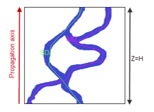
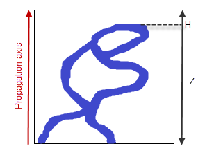
Some common results are extracted by different propagation algorithms. The following drawings illustrate their output results.
Figure 1. Projection of a 3D volume with the pore space in blue and
the solid matrix in white.
(a) Pierced volume, the propagation can travel in the void space along the propagation axis.
(b) Non-pierced volume, the propagation is stopped after having covered the thickness $H$.
In the output object descriptions:
Some common results are extracted by different propagation algorithms. The following drawings illustrate their output results.
 (a) |
 (b) |
(a) Pierced volume, the propagation can travel in the void space along the propagation axis.
(b) Non-pierced volume, the propagation is stopped after having covered the thickness $H$.
In the output object descriptions:
- $Z$ is called the "volume thickness".
- $H$ is called the "void thickness".
- $SD$ is called the "shortest distance".
- $MD$ is called the "maximum distance".
- $H/Z$ is called the "void to volume thickness" ratio.
- $SD/Z$ is called the "shortest distance to volume thickness" ratio.
© 2025 Thermo Fisher Scientific Inc. All rights reserved.