Feret
Contains measurements based on Feret diameter, which is a one-dimensional measurement that estimates how "wide" an object is when projected in a given direction.
Feret diameter is defined as the distance between two parallel tangents of a particle in a given direction, like the measurement by a caliper (see Figure 1).
This definition is extended to 3D with the distance between two tangent planes.
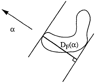
Figure 1. Feret diameter
It is more convenient to consider derivative measurements such as minimum, maximum, or average diameters and their associated orientations when available.
Some examples of Feret derivative measurements are shown in Figure 2.
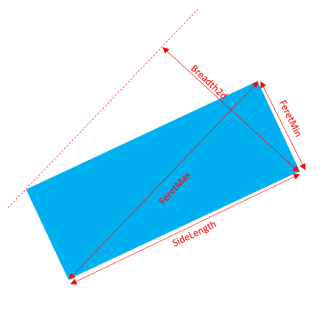
Figure 2. Some Feret derivative measurements
By default the distribution of 2D Feret diameters is made up of a sampling of 10 angles from 0 to 162 degrees with a step of 18 degrees.
This distribution can be customized with the Feret 2D angles attributes.
This distribution can be customized with the Feret 3D angles attributes.
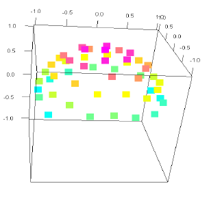
Figure 3. Example of a distribution of 3D angles
The orientations are defined by the couple of angles from spherical coordinates, as often used in mathematics, the azimuthal angle $\theta$ and the polar angle $\phi$.
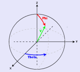
Figure 4. Azimuthal and polar angles
See related example
Feret diameter is defined as the distance between two parallel tangents of a particle in a given direction, like the measurement by a caliper (see Figure 1).
This definition is extended to 3D with the distance between two tangent planes.
Figure 1. Feret diameter
Derivative measurements
Measuring a Feret diameter in a particular direction is usually irrelevant. Even if in 2D it is possible to obtain each Feret diameter of a predefined set of directions (or distribution), this information is not available in 3D.It is more convenient to consider derivative measurements such as minimum, maximum, or average diameters and their associated orientations when available.
Some examples of Feret derivative measurements are shown in Figure 2.
Figure 2. Some Feret derivative measurements
2D Feret diameter distribution
In 2D, Feret diameters are computed along all redefined directions in the range [0; 180[ degrees from which can be determined the minimum, the mean, and the maximum.By default the distribution of 2D Feret diameters is made up of a sampling of 10 angles from 0 to 162 degrees with a step of 18 degrees.
This distribution can be customized with the Feret 2D angles attributes.
3D Feret diameter distribution
In 3D, the distribution is computed to get the predefined number of angles regularly spread around the upper part of the unit sphere. By default a sampling of 31 angles.This distribution can be customized with the Feret 3D angles attributes.
Figure 3. Example of a distribution of 3D angles
The orientations are defined by the couple of angles from spherical coordinates, as often used in mathematics, the azimuthal angle $\theta$ and the polar angle $\phi$.
Figure 4. Azimuthal and polar angles
See related example
Object members
| Measurement name | Description | Element type | Indexing | Physical Information |
|---|---|---|---|---|
| FeretDiameter2d | The Feret diameters distribution expressed in the image calibration unit.
This measurement is a distribution; the Feret diameter is given for each direction through a special index. The corresponding angle can be obtained with the orientation() method of the Feret 2D attributes. |
Floating point | [label, direction] | LENGTH |
| FeretMin2d | The minimum of the 2D Feret diameters expressed in the image calibration unit. | Floating point | [label] | LENGTH |
| FeretMin3d | The minimum of the 3D Feret diameters expressed in the image calibration unit. | Floating point | [label] | LENGTH |
| FeretMinOrientation2d | The angle of the minimum of the 2D Feret diameters, in degrees. | Floating point | [label] | ANGLE |
| FeretMinOrientationPhi3d | The Phi angle of the minimum of the 3D Feret diameters, in degrees and lying in the range [0,90]. | Floating point | [label] | ANGLE |
| FeretMinOrientationTheta3d | The Theta angle of the minimum of the 3D Feret diameters, in degrees and lying in the range [-180,+180[. | Floating point | [label] | ANGLE |
| FeretMax3d | The maximum of the 3D Feret diameters expressed in the image calibration unit. | Floating point | [label] | LENGTH |
| FeretMaxOrientationPhi3d | The Phi angle of the maximum of the 3D Feret diameters, in degrees and lying in the range [0,90]. | Floating point | [label] | ANGLE |
| FeretMaxOrientationTheta3d | The Theta angle of the maximum of the 3D Feret diameters, in degrees and lying in the range [-180,+180[. | Floating point | [label] | ANGLE |
| FeretMaxOrientation2d | The angle of the maximum of the 2D Feret diameters. | Floating point | [label] | ANGLE |
| FeretMax2d | The maximum of the Feret diameters expressed in the image calibration unit. | Floating point | [label] | LENGTH |
| FeretMean2d | The average of the 2D Feret diameters expressed in the image calibration unit. | Floating point | [label] | LENGTH |
| FeretMean3d | The average of the 3D Feret diameters expressed in the image calibration unit. | Floating point | [label] | LENGTH |
| Breadth2d | The Feret diameter orthogonal to the maximum 2D Feret diameter, expressed in the image calibration unit. | Floating point | [label] | LENGTH |
| SideLength2d | The Feret diameter orthogonal to the minimum 2D Feret diameter, expressed in the image calibration unit.
For a square or rectangular object, the maximum Feret diameter does not represent its side length but its diagonal. |
Floating point | [label] | LENGTH |
| FeretRatio2d | The orthogonal diameter to the smallest 2D Feret diameter ratio, which represents an elongation factor.
Let $a$ be the minimal Feret diameters, and let $b$ be the Feret diameter closest to the normal of the minimal Feret diameter. The Feret Shape is the ratio $b/a$. Note that the accuracy highly depends on the number of Feret 2D directions used. |
Floating point | [label] | RATIO |
| FeretRatio3d | The orthogonal diameter to the smallest 3D Feret diameter ratio, which represents an elongation factor.
This shape factor is defined as $(D/d)$, where $d$ is the minimum Feret diameter ( FeretMin3d) and $D$ is the maximum Feret diameter in the orthogonal direction (90 degrees from the minimum Feret diameter, generally not FeretMax3d). Feret 3D diameter measurements rely on sampling in a direction 3D distribution (31 directions by default). |
Floating point | [label] | RATIO |
| FeretInputX2d | The x coordinate of input points of the Feret two-dimensional distribution, expressed in pixel units.
This measurement is a distribution, the Feret diameter is given for each direction through a special index. The corresponding angle can be obtained with the orientation() method of the Feret 2D attributes. |
Floating point | [label, direction] | LENGTH |
| FeretInputY2d | The y coordinate of input point of the Feret two-dimensional distribution, expressed in pixel units.
This measurement is a distribution, the Feret diameter is given for each direction through a special index. The corresponding angle can be obtained with the orientation() method of the Feret 2D attributes. |
Floating point | [label, direction] | LENGTH |
| FeretOutputX2d | The x coordinate of output point of the Feret two-dimensional distribution, expressed in pixel units.
This measurement is a distribution, the Feret diameter is given for each direction through a special index. The corresponding angle can be obtained with the orientation() method of the Feret 2D attributes. |
Floating point | [label, direction] | LENGTH |
| FeretOutputY2d | The y coordinate of output point of the Feret two-dimensional distribution, expressed in pixel units.
This measurement is a distribution, the Feret diameter is given for each direction through a special index. The corresponding angle can be obtained with the orientation() method of the Feret 2D attributes. |
Floating point | [label, direction] | LENGTH |
| Breadth3d | The largest distance between two parallel lines touching the object without intersecting it, and lying in a plane orthogonal to the maximum 3D Feret diameter, expressed in the image calibration unit.
The direction of the largest 3D Feret diameter is first determined (FeretMaxOrientationPhi3d, FeretMaxOrientationTheta3d). The breadth measurement is then evaluated as the maximum 2D Feret diameter in planes orthogonal to this direction. 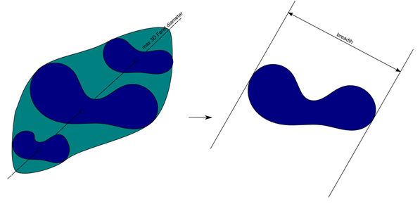 Figure 4. Example of breadth 3D measure |
Floating point | [label] | LENGTH |
| BreadthOrientationPhi3d | The Phi angle of the Breadth orientation, in degrees and lying in the range [0,90]. | Floating point | [label] | ANGLE |
| BreadthOrientationTheta3d | The Theta angle of the Breadth orientation, in degrees and lying in the range [-180,+180[. | Floating point | [label] | ANGLE |
| Thickness3d | The largest distance between two parallel lines touching the object without intersecting it, and lying in a plane orthogonal to the maximum 3D Feret diameter and also orthogonal to the Breadth, expressed in the image calibration unit.
The Breadth3d measurement is first determined, the thickness measurement is then evaluated as the maximum Feret diameter orthogonal to the Breadth3d and FeretMax3d directions. |
Floating point | [label] | LENGTH |
| ThicknessOrientationPhi3d | The Phi angle of the Thickness orientation, in degrees and lying in the range [0,90]. | Floating point | [label] | ANGLE |
| ThicknessOrientationTheta3d | The Theta angle of the Thickness orientation, in degrees and lying in the range [-180,+180[. | Floating point | [label] | ANGLE |
| FeretMaxInputX3d | The x coordinate of the FeretMax3d diameter input point, expressed in the image calibration unit. | Floating point | [label] | LENGTH |
| FeretMaxInputY3d | The y coordinate of the FeretMax3d diameter input point, expressed in the image calibration unit. | Floating point | [label] | LENGTH |
| FeretMaxInputZ3d | The z coordinate of the FeretMax3d diameter input point, expressed in the image calibration unit. | Floating point | [label] | LENGTH |
| FeretMaxOutputX3d | The x coordinate of the FeretMax3d diameter output point, expressed in the image calibration unit. | Floating point | [label] | LENGTH |
| FeretMaxOutputY3d | The y coordinate of the FeretMax3d diameter output point, expressed in the image calibration unit. | Floating point | [label] | LENGTH |
| FeretMaxOutputZ3d | The z coordinate of the FeretMax3d diameter output point, expressed in the image calibration unit. | Floating point | [label] | LENGTH |
| FeretMinInputX3d | The x coordinate of the FeretMin3d diameter input point, expressed in the image calibration unit. | Floating point | [label] | LENGTH |
| FeretMinInputY3d | The y coordinate of the FeretMin3d diameter input point, expressed in the image calibration unit. | Floating point | [label] | LENGTH |
| FeretMinInputZ3d | The z coordinate of the FeretMin3d diameter input point, expressed in the image calibration unit. | Floating point | [label] | LENGTH |
| FeretMinOutputX3d | The x coordinate of the FeretMin3d diameter output point, expressed in the image calibration unit. | Floating point | [label] | LENGTH |
| FeretMinOutputY3d | The y coordinate of the FeretMin3d diameter output point, expressed in the image calibration unit. | Floating point | [label] | LENGTH |
| FeretMinOutputZ3d | The z coordinate of the FeretMin3d diameter output point, expressed in the image calibration unit. | Floating point | [label] | LENGTH |
| BreadthInputX3d | The x coordinate of the Breadth3d diameter input point, expressed in the image calibration unit. | Floating point | [label] | LENGTH |
| BreadthInputY3d | The y coordinate of the Breadth3d diameter input point, expressed in the image calibration unit. | Floating point | [label] | LENGTH |
| BreadthInputZ3d | The z coordinate of the Breadth3d diameter input point, expressed in the image calibration unit. | Floating point | [label] | LENGTH |
| BreadthOutputX3d | The x coordinate of the Breadth3d diameter output point, expressed in the image calibration unit. | Floating point | [label] | LENGTH |
| BreadthOutputY3d | The y coordinate of the Breadth3d diameter output point, expressed in the image calibration unit. | Floating point | [label] | LENGTH |
| BreadthOutputZ3d | The z coordinate of the Breadth3d diameter output point, expressed in the image calibration unit. | Floating point | [label] | LENGTH |
| ThicknessInputX3d | The x coordinate of the Thickness3d diameter input point, expressed in the image calibration unit. | Floating point | [label] | LENGTH |
| ThicknessInputY3d | The y coordinate of the Thickness3d diameter input point, expressed in the image calibration unit. | Floating point | [label] | LENGTH |
| ThicknessInputZ3d | The z coordinate of the Thickness3d diameter input point, expressed in the image calibration unit. | Floating point | [label] | LENGTH |
| ThicknessOutputX3d | x coordinate of the Thickness3d diameter output point, expressed in the image calibration unit. | Floating point | [label] | LENGTH |
| ThicknessOutputY3d | The y coordinate of the Thickness3d diameter output point, expressed in the image calibration unit. | Floating point | [label] | LENGTH |
| ThicknessOutputZ3d | The z coordinate of the Thickness3d diameter output point, expressed in the image calibration unit. | Floating point | [label] | LENGTH |
Object methods
| Method | Description |
|---|---|
| void toDataFrame() |
Convert the measurement to an IOLink.DataFrame One or more "index" columns will be added at the beginning of the dataframe to identify the different elements. For instance:
|
| Method | Description |
|---|---|
| void ToDataFrame() |
Convert the measurement to an IOLink.DataFrame One or more "index" columns will be added at the beginning of the dataframe to identify the different elements. For instance:
|
| Method | Description |
|---|---|
| void to_data_frame() |
Convert the measurement to an IOLink.DataFrame One or more "index" columns will be added at the beginning of the dataframe to identify the different elements. For instance:
|
© 2026 Thermo Fisher Scientific Inc. All rights reserved.