Labeling2d
Assigns the same label to each connected component pixel set of a two-dimensional binary or label image.
Access to parameter description
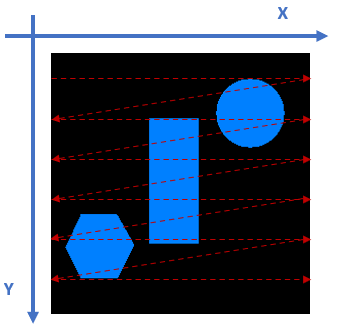
The connected-component labeling algorithm scans the input image from its first to its last row along the y-axis, and from its first to its last column along the x-axis. With a standard visualization of a 2D image considering the image origin in the top left corner and the y-axis down, this algorithm scans the input image from top to bottom and left to right.
A connected component refers here to a set of pixels with a same value that are connected or contiguous to each other. They form a region or object within the image. The connectivity between pixels is determined by 4-connectivity, or 8-connectivity and can be defined by the neighborhood parameter.
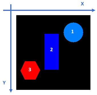
Each pixel of the same connected component (or object) takes the same value, and each object is assigned to a different value, starting from value 1. The assigned gray level (or label) depends on the location of the object in the image. The maximum gray level value gives the total number of objects in the original binary or label image, which means that all objects have consecutive indices.
Figure 1. 2D connected-component labeling: (left) scanning order, (right) label assignation
A label image pixel may be represented by 8, 16, or 32 bits.
By default, the output image type is defined by the labelType parameter. If the number of labels exceeds its capacity, then the output image is automatically converted to the upper type to be able to manage the number of labels. The processing is then restarted from the beginning to produce the result in the selected new data type. To optimize the computation, it is important to select a relevant type for the output. Selecting an 8-bit type for an image containing more than 65535 objects will produce the expected result, but will compute it in much more time than by selecting a 32-bit output type directly. On the contrary, selecting a 32-bit type for an image containing fewer than 256 objects will produce the result in nearly optimal time but will use much more memory than necessary.
See also
See related examples
Access to parameter description
The connected-component labeling algorithm scans the input image from its first to its last row along the y-axis, and from its first to its last column along the x-axis. With a standard visualization of a 2D image considering the image origin in the top left corner and the y-axis down, this algorithm scans the input image from top to bottom and left to right.
A connected component refers here to a set of pixels with a same value that are connected or contiguous to each other. They form a region or object within the image. The connectivity between pixels is determined by 4-connectivity, or 8-connectivity and can be defined by the neighborhood parameter.
Each pixel of the same connected component (or object) takes the same value, and each object is assigned to a different value, starting from value 1. The assigned gray level (or label) depends on the location of the object in the image. The maximum gray level value gives the total number of objects in the original binary or label image, which means that all objects have consecutive indices.
 |
 |
A label image pixel may be represented by 8, 16, or 32 bits.
By default, the output image type is defined by the labelType parameter. If the number of labels exceeds its capacity, then the output image is automatically converted to the upper type to be able to manage the number of labels. The processing is then restarted from the beginning to produce the result in the selected new data type. To optimize the computation, it is important to select a relevant type for the output. Selecting an 8-bit type for an image containing more than 65535 objects will produce the expected result, but will compute it in much more time than by selecting a 32-bit output type directly. On the contrary, selecting a 32-bit type for an image containing fewer than 256 objects will produce the result in nearly optimal time but will use much more memory than necessary.
See also
See related examples
Function Syntax
This function returns outputLabelImage.
// Function prototype
std::shared_ptr< iolink::ImageView >
labeling2d( std::shared_ptr< iolink::ImageView > inputObjectImage,
            Labeling2d::LabelType labelType,
            Labeling2d::Neighborhood neighborhood,
            std::shared_ptr< iolink::ImageView > outputLabelImage = nullptr );
This function returns outputLabelImage.
// Function prototype.
labeling_2d(input_object_image: idt.ImageType,
            label_type: Union[Literal["LABEL_8_BIT"],Literal["LABEL_16_BIT"],Literal["LABEL_32_BIT"],Labeling2d.LabelType] = Labeling2d.LabelType.LABEL_16_BIT,
            neighborhood: Union[Literal["CONNECTIVITY_4"],Literal["CONNECTIVITY_8"],Labeling2d.Neighborhood] = Labeling2d.Neighborhood.CONNECTIVITY_8,
            output_label_image: idt.ImageType = None) -> idt.ImageType
This function returns outputLabelImage.
// Function prototype.
public static IOLink.ImageView
Labeling2d( IOLink.ImageView inputObjectImage,
            Labeling2d.LabelType labelType = ImageDev.Labeling2d.LabelType.LABEL_16_BIT,
            Labeling2d.Neighborhood neighborhood = ImageDev.Labeling2d.Neighborhood.CONNECTIVITY_8,
            IOLink.ImageView outputLabelImage = null );
Class Syntax
Parameters
| Parameter Name | Description | Type | Supported Values | Default Value | |||||||
|---|---|---|---|---|---|---|---|---|---|---|---|
 |
inputObjectImage |
The input binary or label image. | Image | Binary or Label | nullptr | ||||||
|
labelType |
The minimum output data type. Automatically changed if not sufficient to encode all labels.
|
Enumeration | LABEL_16_BIT | |||||||
|
neighborhood |
The 2D neighborhood configuration defining the connected components.
|
Enumeration | CONNECTIVITY_8 | |||||||
 |
outputLabelImage |
The output label image. Its dimensions are forced to the same values as the input image. Its type depends on the number of objects and the labelType parameter. | Image | nullptr | |||||||
| Parameter Name | Description | Type | Supported Values | Default Value | |||||||
|---|---|---|---|---|---|---|---|---|---|---|---|
|
input_object_image |
The input binary or label image. | image | Binary or Label | None | ||||||
|
label_type |
The minimum output data type. Automatically changed if not sufficient to encode all labels.
|
enumeration | LABEL_16_BIT | |||||||
|
neighborhood |
The 2D neighborhood configuration defining the connected components.
|
enumeration | CONNECTIVITY_8 | |||||||
|
output_label_image |
The output label image. Its dimensions are forced to the same values as the input image. Its type depends on the number of objects and the labelType parameter. | image | None | |||||||
| Parameter Name | Description | Type | Supported Values | Default Value | |||||||
|---|---|---|---|---|---|---|---|---|---|---|---|
|
inputObjectImage |
The input binary or label image. | Image | Binary or Label | null | ||||||
|
labelType |
The minimum output data type. Automatically changed if not sufficient to encode all labels.
|
Enumeration | LABEL_16_BIT | |||||||
|
neighborhood |
The 2D neighborhood configuration defining the connected components.
|
Enumeration | CONNECTIVITY_8 | |||||||
|
outputLabelImage |
The output label image. Its dimensions are forced to the same values as the input image. Its type depends on the number of objects and the labelType parameter. | Image | null | |||||||
Object Examples
auto polystyrene_sep = readVipImage( std::string( IMAGEDEVDATA_IMAGES_FOLDER ) + "polystyrene_sep.vip" );

Labeling2d labeling2dAlgo;
labeling2dAlgo.setInputObjectImage( polystyrene_sep );
labeling2dAlgo.setLabelType( Labeling2d::LabelType::LABEL_8_BIT );
labeling2dAlgo.setNeighborhood( Labeling2d::Neighborhood::CONNECTIVITY_8 );
labeling2dAlgo.execute();

std::cout << "outputLabelImage:" << labeling2dAlgo.outputLabelImage()->toString();
polystyrene_sep = imagedev.read_vip_image(imagedev_data.get_image_path("polystyrene_sep.vip"))

labeling_2d_algo = imagedev.Labeling2d()
labeling_2d_algo.input_object_image = polystyrene_sep
labeling_2d_algo.label_type = imagedev.Labeling2d.LABEL_8_BIT
labeling_2d_algo.neighborhood = imagedev.Labeling2d.CONNECTIVITY_8
labeling_2d_algo.execute()

print("output_label_image:", str(labeling_2d_algo.output_label_image))
ImageView polystyrene_sep = Data.ReadVipImage( @"Data/images/polystyrene_sep.vip" );

Labeling2d labeling2dAlgo = new Labeling2d
{
    inputObjectImage = polystyrene_sep,
    labelType = Labeling2d.LabelType.LABEL_8_BIT,
    neighborhood = Labeling2d.Neighborhood.CONNECTIVITY_8
};
labeling2dAlgo.Execute();

Console.WriteLine( "outputLabelImage:" + labeling2dAlgo.outputLabelImage.ToString() );
Function Examples
auto polystyrene_sep = readVipImage( std::string( IMAGEDEVDATA_IMAGES_FOLDER ) + "polystyrene_sep.vip" );

auto result = labeling2d( polystyrene_sep, Labeling2d::LabelType::LABEL_8_BIT, Labeling2d::Neighborhood::CONNECTIVITY_8 );

std::cout << "outputLabelImage:" << result->toString();
polystyrene_sep = imagedev.read_vip_image(imagedev_data.get_image_path("polystyrene_sep.vip"))

result = imagedev.labeling_2d(polystyrene_sep, imagedev.Labeling2d.LABEL_8_BIT, imagedev.Labeling2d.CONNECTIVITY_8)

print("output_label_image:", str(result))
ImageView polystyrene_sep = Data.ReadVipImage( @"Data/images/polystyrene_sep.vip" );

IOLink.ImageView result = Processing.Labeling2d( polystyrene_sep, Labeling2d.LabelType.LABEL_8_BIT, Labeling2d.Neighborhood.CONNECTIVITY_8 );

Console.WriteLine( "outputLabelImage:" + result.ToString() );
© 2026 Thermo Fisher Scientific Inc. All rights reserved.