Pore Analysis
This example chains several classical image processing algorithms on a three-dimensional digital rocks image. It extracts several features characterizing the pores contained in shale rock volume.
The input image is a 3D sample of shale rock made up of minerals, organic matter, and pores.
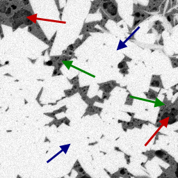
Figure 1. Original image with (red) pores, (green) organic-matter grains, and (blue) minerals
First, this example applies the BilateralFilter3d to denoise the input image while preserving the edges of the different materials.
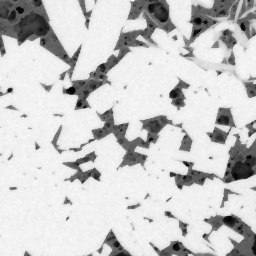
Figure 2. Denoised image
A first thresholding operation is done to isolate the darker objects corresponding to the pores.
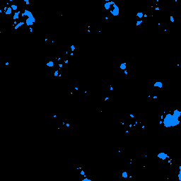
Figure 3. Rough binarization of the pores
An erosion is performed to isolate the pores from the organic matters and build pore markers.
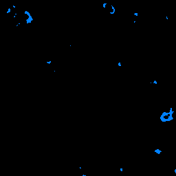
Figure 4. Eroded pore markers
A second thresholding is applied to detect the minerals.
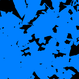
Figure 5. Rough binarization of the minerals
Then, the AddObjectToLabel algorithm is applied to create a label image that merges pore markers as label 1 with background markers as label 2.
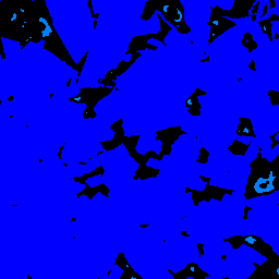
Figure 6. Merged markers: (light blue) pores and (dark blue) organic matters and minerals
The denoised image is processed by the GradientOperator3d algorithm to reveal the edges of the different phases.
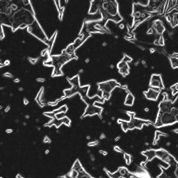
Figure 7. Gradient of the denoised image
This gradient image can be used as a landscape image for the watershed algorithm. MarkerBasedWatershed3d is applied on this image with the merged markers image to detect the separation surfaces between pores and background.
The FillHoles2d algorithm is applied on each 2D slice of the resulting volume to fill the pores. A BorderKill operation is also applied to remove pores that are not entirely visible in the image.
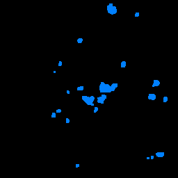
Figure 8. Result after filling pores and rejecting pores intersecting the image borders
The image is labeled to assign the same intensity to all voxels belonging to the same connected pore.
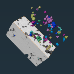
Figure 9. Original image and labeled pores
Some global measurements are computed to extract the number of detected pores and the phase fraction represented by the pores.
Finally, three measurements are computed for each pore: its volume, the diameter of a sphere of the same volume, and a shape factor indicating if the pore is spherical or not. The corresponding results are displayed in the console for the first pores of the volume.
See also
Figure 1. Original image with (red) pores, (green) organic-matter grains, and (blue) minerals
First, this example applies the BilateralFilter3d to denoise the input image while preserving the edges of the different materials.
Figure 2. Denoised image
A first thresholding operation is done to isolate the darker objects corresponding to the pores.
Figure 3. Rough binarization of the pores
An erosion is performed to isolate the pores from the organic matters and build pore markers.
Figure 4. Eroded pore markers
A second thresholding is applied to detect the minerals.
Figure 5. Rough binarization of the minerals
Then, the AddObjectToLabel algorithm is applied to create a label image that merges pore markers as label 1 with background markers as label 2.
Figure 6. Merged markers: (light blue) pores and (dark blue) organic matters and minerals
The denoised image is processed by the GradientOperator3d algorithm to reveal the edges of the different phases.
Figure 7. Gradient of the denoised image
This gradient image can be used as a landscape image for the watershed algorithm. MarkerBasedWatershed3d is applied on this image with the merged markers image to detect the separation surfaces between pores and background.
The FillHoles2d algorithm is applied on each 2D slice of the resulting volume to fill the pores. A BorderKill operation is also applied to remove pores that are not entirely visible in the image.
Figure 8. Result after filling pores and rejecting pores intersecting the image borders
The image is labeled to assign the same intensity to all voxels belonging to the same connected pore.
Figure 9. Original image and labeled pores
Some global measurements are computed to extract the number of detected pores and the phase fraction represented by the pores.
- Pore volume fraction = 1.84%
- Pore number = 114
Finally, three measurements are computed for each pore: its volume, the diameter of a sphere of the same volume, and a shape factor indicating if the pore is spherical or not. The corresponding results are displayed in the console for the first pores of the volume.
| Pore | EquivalentDiameter | Volume3d | InverseSphericity3d |
| 1 | 11.43 | 781.90 | 2.12 |
| 2 | 13.42 | 1266.16 | 1.72 |
| 3 | 6.91 | 172.88 | 1.14 |
| 4 | 9.27 | 558.92 | 1.89 |
#include <ImageDev/Data/ImageViewHelper.h>
#include <ImageDev/Data/NativeMeasurements.h>
#include <ImageDev/ImageDev.h>
#include <ioformat/IOFormat.h>

using namespace imagedev;
using namespace ioformat;
using namespace iolink;

int
main()
{
    // Initialize the ImageDev library if not done
    if ( imagedev::isInitialized() == false )
        imagedev::init();

    // Open a standard tif file and display the image properties
    auto imageInput = readImage( std::string( IMAGEDEVDATA_IMAGES_FOLDER ) + "shale.am" );

    // Preprocess the input with a bilateral filter for denoising
    auto imageDenoised = bilateralFilter3d( imageInput, 3, 3, 3, 20, BilateralFilter3d::BILATERAL );

    // STEP 1: Pore segmentation with the watershed algorithm
    // Threshold the low graylevels (pore markers)
    auto imageLowBin =
        thresholdingByCriterion( imageDenoised, ThresholdingByCriterion::ComparisonCriterion::LESS_THAN, 40 );

    // Slightly erode these markers in order to avoid contact with the high level markers
    auto imageLowEro = erosion3d( imageLowBin, 1, Erosion3d::CONNECTIVITY_26 );

    // Initialize the marker image (label 1)
    auto imageLowLab = convertImage( imageLowEro, ConvertImage::LABEL_16_BIT );

    // Threshold the high graylevels (mineral markers)
    auto imageHighBin =
        thresholdingByCriterion( imageDenoised, ThresholdingByCriterion::ComparisonCriterion::GREATER_THAN, 90 );

    // Merge high intensity markers with label 2
    auto imageMarkers = addObjectToLabel( imageHighBin, imageLowLab, 2 );

    // Extract the gradient to build the relief image for watershed
    auto resultGrad =
        gradientOperator3d( imageDenoised, GradientOperator3d::CANNY, GradientOperator3d::AMPLITUDE_MAXIMUM, 60 );

    // Perform the Watershed to detect pore boundaries
    auto imageWatershed = markerBasedWatershed3d( resultGrad.outputAmplitudeImage,
                                                  imageMarkers,
                                                  MarkerBasedWatershed3d::REPEATABLE,
                                                  MarkerBasedWatershed3d::LINES,
                                                  MarkerBasedWatershed3d::CONNECTIVITY_26 );

    // Fill all pores in each 2D slice of the volume
    setDimensionalInterpretation( imageWatershed, ImageTypeId::IMAGE_SEQUENCE );
    auto imageFilled = fillHoles2d( imageWatershed, FillHoles2d::CONNECTIVITY_4 );
    setDimensionalInterpretation( imageFilled, ImageTypeId::VOLUME );

    // Remove pores touching the image border
    auto imageInside = borderKill( imageFilled, BorderKill::Neighborhood::CONNECTIVITY_26 );

    // Assign labels to the pores
    auto imagePores = labeling3d( imageInside, Labeling3d::LABEL_16_BIT, Labeling3d::CONNECTIVITY_26 );

    // STEP 2: Pore quantification
    // Compute the pore volume percentage
    auto poreVolume = intensityIntegral3d( imageInside );
    std::cout << "  - Pore volume fraction = " << ( 100.0 * poreVolume->volumeFraction() ) << "%" << std::endl;

    // Compute the pore number
    auto poreCount = objectCount( imagePores );
    std::cout << "  - Pore number = " << poreCount.outputMeasurement->count( 0 ) << std::endl;

    // Define the analysis features to be computed
    AnalysisMsr::Ptr analysis = AnalysisMsr::Ptr( new AnalysisMsr() );
    auto diameter = analysis->select( NativeMeasurements::equivalentDiameter );
    auto volume = analysis->select( NativeMeasurements::volume3d );
    auto shape = analysis->select( NativeMeasurements::inverseSphericity3d );

    // Launch the feature extraction on the segmented image
    labelAnalysis( imagePores, NULL, analysis );
    std::cout << "Pore\t" << diameter->name() << "\t" << volume->name() << "\t" << shape->name() << std::endl;
    // Print the analysis results for 5% of the pores
    for ( int i = 0; i < ( int )( analysis->labelCount() / 20 ); i++ )
    {
        std::cout << ( i + 1 ) << "\t\t" << diameter->value( i ) << "\t\t\t" << volume->value( i ) << "\t\t"
                  << shape->value( i ) << std::endl;
    }

    // Save the segmented image with IOFormat
    writeView( imagePores, R"(T06_02_output.tif)" );

    // Close the ImageDev library
    imagedev::finish();

    return 0;
}
using System;
using ImageDev;
using IOLink;
using IOFormat;

namespace T06_02_PoreAnalysis
{
    class Program
    {
        static void Main( string[] args )
        {
            // Initialize the ImageDev library if not done
            if ( Initialization.IsInitialized() == false )
                Initialization.Init();

            // Open a standard tif file and display the image properties
            ImageView imageInput = IOFormat.ViewIO.ReadImage( @"Data/images/shale.am" ) as ImageView;

            // Preprocess the input with a bilateral filter for denoising
            ImageView imageDenoised =
                Processing.BilateralFilter3d( imageInput, 3, 3, 3, 20, BilateralFilter3d.FilterMode.BILATERAL )
                    as ImageView;

            // STEP 1: Pore segmentation with the watershed algorithm
            // Threshold the low graylevels (pore markers)
            ImageView imageLowBin = Processing.ThresholdingByCriterion(
                imageDenoised, ThresholdingByCriterion.ComparisonCriterion.LESS_THAN, 40 ) as ImageView;

            // Slightly erode these markers in order to avoid contact with the high level markers
            ImageView imageLowEro =
                Processing.Erosion3d( imageLowBin, 1, Erosion3d.Neighborhood.CONNECTIVITY_26 ) as ImageView;

            // Initialize the marker image (label 1)
            ImageView imageLowLab =
                Processing.ConvertImage( imageLowEro, ConvertImage.OutputType.LABEL_16_BIT ) as ImageView;

            // Threshold the high graylevels (mineral markers)
            ImageView imageHighBin = Processing.ThresholdingByCriterion(
                imageDenoised, ThresholdingByCriterion.ComparisonCriterion.GREATER_THAN, 90 ) as ImageView;

            // Merge high intensity markers with label 2
            ImageView imageMarkers = Processing.AddObjectToLabel( imageHighBin, imageLowLab, 2 ) as ImageView;

            // Extract the gradient to build the relief image for watershed
            var resultGrad = Processing.GradientOperator3d( imageDenoised,
                                                            GradientOperator3d.GradientOperator.CANNY,
                                                            GradientOperator3d.GradientMode.AMPLITUDE_MAXIMUM,
                                                            60 );

            // Perform the Watershed to detect pore boundaries
            ImageView imageWatershed =
                Processing.MarkerBasedWatershed3d( resultGrad.outputAmplitudeImage,
                                                   imageMarkers,
                                                   MarkerBasedWatershed3d.AlgorithmMode.REPEATABLE,
                                                   MarkerBasedWatershed3d.OutputType.LINES,
                                                   MarkerBasedWatershed3d.Neighborhood.CONNECTIVITY_26 ) as ImageView;

            // Fill all pores in each 2D slice of the volume
            Data.SetDimensionalInterpretation( imageWatershed, ImageTypeId.IMAGE_SEQUENCE );
            ImageView imageFilled = Processing.FillHoles2d( imageWatershed, FillHoles2d.Neighborhood.CONNECTIVITY_4 );
            Data.SetDimensionalInterpretation( imageFilled, ImageTypeId.VOLUME );

            // Remove pores touching the image border
            ImageView imageInside =
                Processing.BorderKill( imageFilled, BorderKill.Neighborhood.CONNECTIVITY_26 ) as ImageView;

            // Assign labels to the pores
            ImageView imagePores = Processing.Labeling3d( imageInside,
                                                          Labeling3d.LabelType.LABEL_16_BIT,
                                                          Labeling3d.Neighborhood.CONNECTIVITY_26 ) as ImageView;

            // STEP 2: Pore quantification
            // Compute the pore volume percentage
            var poreVolume = Processing.IntensityIntegral3d( imageInside );
            Console.WriteLine(
                "  - Pore volume fraction = " + ( 100.0 * poreVolume.volumeFraction() ).ToString( "0.00" ) + " %" );

            // Compute the pore number
            var poreCount = Processing.ObjectCount( imagePores );
            Console.WriteLine( "  - Pore number = " + poreCount.outputMeasurement.count( 0 ) );

            // Define the analysis features to be computed
            AnalysisMsr analysis = new AnalysisMsr();
            var diameter = analysis.Select( NativeMeasurements.EquivalentDiameter );
            var volume = analysis.Select( NativeMeasurements.Volume3d );
            var shape = analysis.Select( NativeMeasurements.InverseSphericity3d );

            // Launch the feature extraction on the segmented image
            Processing.LabelAnalysis( imagePores, null, analysis );
            Console.WriteLine("Pore\t" + diameter.Name() + "\t" + volume.Name() + "\t" + shape.Name() );
            // Print the analysis results for 5% of the pores
            for ( int i = 0; i < ( int )( analysis.LabelCount() / 20 ); i++ )
            {
                Console.WriteLine( ( i + 1 ) + "\t\t" + diameter.Value( i ).ToString( "0.00" ) + "\t\t\t" +
                                   volume.Value( i ).ToString( "0.00" ) + "\t\t" +
                                   shape.Value( i ).ToString( "0.00" ) );
            }

            // Save the segmented image with IOFormat
            IOFormat.ViewIO.WriteView( imagePores, @"T06_02_output.tif" );

            // Close the ImageDev library
            Initialization.Finish();
        }
    }
}
import imagedev
import imagedev_data
import ioformat
import iolink

# Initialize the ImageDev library if not done
if (imagedev.is_initialized() == False): imagedev.init()

# Open and display a tif file
image_input = ioformat.read_image(imagedev_data.get_image_path("shale.am"))

# Preprocess the input with a bilateral filter for denoising
image_denoised = imagedev.bilateral_filter_3d(image_input)

# STEP 1: Pore segmentation with the watershed algorithm
# Threshold the low graylevels (pore markers)
image_low_bin = imagedev.thresholding_by_criterion(\
  image_denoised, imagedev.ThresholdingByCriterion.ComparisonCriterion.LESS_THAN, 40)

# Slightly erode these markers in order to avoid contact with the high level markers
image_low_ero = imagedev.erosion_3d(image_low_bin, 1)

# Initialize the marker image (label 1)
image_low_lab = imagedev.convert_image(image_low_ero, imagedev.ConvertImage.LABEL_16_BIT)

# Threshold the high graylevels (mineral markers)
image_high_bin = imagedev.thresholding_by_criterion(\
  image_denoised, imagedev.ThresholdingByCriterion.ComparisonCriterion.GREATER_THAN, 90)

# Merge high intensity markers with label 2
image_markers = imagedev.add_object_to_label(image_high_bin, image_low_lab, 2)

# Extract the gradient to build the relief image for watershed
_, _, _, image_grad = imagedev.gradient_operator_3d(image_denoised, imagedev.GradientOperator3d.CANNY)

# Perform the Watershed to detect pore boundaries
image_watershed = imagedev.marker_based_watershed_3d(image_grad, image_markers,\
                                                     output_type=imagedev.MarkerBasedWatershed3d.OutputType.LINES)

# Fill all pores in each slice of the volume
imagedev.set_dimensional_interpretation(image_watershed, iolink.ImageTypeId.IMAGE_SEQUENCE)
image_filled = imagedev.fill_holes_2d(image_watershed, imagedev.FillHoles2d.CONNECTIVITY_4)
imagedev.set_dimensional_interpretation(image_filled, iolink.ImageTypeId.VOLUME)

# Remove pores touching the image border
image_inside = imagedev.border_kill(image_filled)

# Assign labels to the pores
image_pores = imagedev.labeling_3d(image_inside)

# STEP 2: Pore quantification
# Compute the pore volume percentage
pore_volume = imagedev.intensity_integral_3d(image_inside)
print("  - Pore volume fraction = " + "{:.2f}".format(pore_volume.volume_fraction()*100) + "%")

# Compute the pore number
_, pore_count = imagedev.object_count(image_pores)
print("  - Pore number = " + str(pore_count.count(0)))

# Define the analysis features to be computed
analysis = imagedev.AnalysisMsr()
diameter = analysis.select(imagedev.native_measurements.EquivalentDiameter)
volume = analysis.select(imagedev.native_measurements.Volume3d)
shape = analysis.select(imagedev.native_measurements.InverseSphericity3d)

# Launch the feature extraction on the segmented image
imagedev.label_analysis(image_pores, None, analysis)
print("Pore\t" + diameter.name + "\t" + volume.name + "\t" + shape.name)
# Print the analysis results for 5% of the pores
for i in range(int(analysis.label_count/20)):
  print(str(i+1) + '\t\t\t' + "{:.2f}".format(diameter.value(i)) +'\t\t\t\t' + "{:.2f}".format(volume.value(i)) +\
    '\t\t' + "{:.2f}".format(shape.value(i)))

# Save the segmented image with IOFormat
ioformat.write_view(image_pores, "T06_02_output.tif")

# Close the ImageDev library
imagedev.finish()
See also