GeodesicPropagation2d
Performs a geodesic propagation on a two-dimensional binary image.
Access to parameter description
For an introduction:
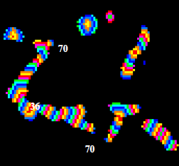
The following image contains the result of a geodesic propagation on an image to differentiate the various gray level values appearing as stripes or rings. For the largest particle, $t_X(x)$ has a minimum of 36 and then values spread until 70 at the extremities. It means that the shortest distance is 36 and the length of the particle can be considered as equal to 70. For particles close to a disk, the geodesic center is located at the center of the particle, and points with the same gray level value are concentric rings.

Figure 1. Geodesic propagation
The geodesic function has a minimum for each particle that is either a point or a region, named the geodesic center of the particle. The value of this minimum is named the geodesic radius of the particle, as a circle drawn from any of the geodesic center points with such a radius will hit the extremities of the particle.
The maximum is reached at points usually located at the extremities of the particles, named geodesic ends. The value of this maximum is named the geodesic length and is seldom equal to 2 times the geodesic radius. In the case of a disk, the center is the geodesic center and the diameter is the geodesic diameter.
Note: This algorithm does not take into account the input image calibration. The output pixel values are systematically indicating the propagation distance in pixel unit.
Reference:
P. Soille, Morphological Image Analysis. Principles and Applications, Second Edition, Springer-Verlag, Berlin, pp.227-231, 2003.
See also
Access to parameter description
For an introduction:
- section Mathematical Morphology
- section Geodesic Transformations
The following image contains the result of a geodesic propagation on an image to differentiate the various gray level values appearing as stripes or rings. For the largest particle, $t_X(x)$ has a minimum of 36 and then values spread until 70 at the extremities. It means that the shortest distance is 36 and the length of the particle can be considered as equal to 70. For particles close to a disk, the geodesic center is located at the center of the particle, and points with the same gray level value are concentric rings.

Figure 1. Geodesic propagation
The geodesic function has a minimum for each particle that is either a point or a region, named the geodesic center of the particle. The value of this minimum is named the geodesic radius of the particle, as a circle drawn from any of the geodesic center points with such a radius will hit the extremities of the particle.
The maximum is reached at points usually located at the extremities of the particles, named geodesic ends. The value of this maximum is named the geodesic length and is seldom equal to 2 times the geodesic radius. In the case of a disk, the center is the geodesic center and the diameter is the geodesic diameter.
Note: This algorithm does not take into account the input image calibration. The output pixel values are systematically indicating the propagation distance in pixel unit.
Reference:
P. Soille, Morphological Image Analysis. Principles and Applications, Second Edition, Springer-Verlag, Berlin, pp.227-231, 2003.
See also
Function Syntax
This function returns outputImage.
// Function prototype
std::shared_ptr< iolink::ImageView >
geodesicPropagation2d( std::shared_ptr< iolink::ImageView > inputBinaryImage, std::shared_ptr< iolink::ImageView > outputImage = NULL );
This function returns outputImage.
// Function prototype.
geodesic_propagation_2d( input_binary_image, output_image = None )
This function returns outputImage.
// Function prototype.
public static IOLink.ImageView
GeodesicPropagation2d( IOLink.ImageView inputBinaryImage, IOLink.ImageView outputImage = null );
Class Syntax
Parameters
| Class Name | GeodesicPropagation2d |
|---|
| Parameter Name | Description | Type | Supported Values | Default Value | |
|---|---|---|---|---|---|
 |
inputBinaryImage |
The binary input image. | Image | Binary | nullptr |
 |
outputImage |
The output image. Its dimensions are forced to the same values as the input. Its type is forced to signed 16-bit integer | Image | nullptr | |
Object Examples
auto polystyrene_sep = readVipImage( std::string( IMAGEDEVDATA_IMAGES_FOLDER ) + "polystyrene_sep.vip" );

GeodesicPropagation2d geodesicPropagation2dAlgo;
geodesicPropagation2dAlgo.setInputBinaryImage( polystyrene_sep );
geodesicPropagation2dAlgo.execute();

std::cout << "outputImage:" << geodesicPropagation2dAlgo.outputImage()->toString();
polystyrene_sep = imagedev.read_vip_image(imagedev_data.get_image_path("polystyrene_sep.vip"))

geodesic_propagation_2d_algo = imagedev.GeodesicPropagation2d()
geodesic_propagation_2d_algo.input_binary_image = polystyrene_sep
geodesic_propagation_2d_algo.execute()

print( "output_image:", str( geodesic_propagation_2d_algo.output_image ) )
ImageView polystyrene_sep = Data.ReadVipImage( @"Data/images/polystyrene_sep.vip" );

GeodesicPropagation2d geodesicPropagation2dAlgo = new GeodesicPropagation2d
{
    inputBinaryImage = polystyrene_sep
};
geodesicPropagation2dAlgo.Execute();

Console.WriteLine( "outputImage:" + geodesicPropagation2dAlgo.outputImage.ToString() );
Function Examples
auto polystyrene_sep = readVipImage( std::string( IMAGEDEVDATA_IMAGES_FOLDER ) + "polystyrene_sep.vip" );

auto result = geodesicPropagation2d( polystyrene_sep );

std::cout << "outputImage:" << result->toString();
polystyrene_sep = imagedev.read_vip_image(imagedev_data.get_image_path("polystyrene_sep.vip"))

result = imagedev.geodesic_propagation_2d( polystyrene_sep )

print( "output_image:", str( result ) )
ImageView polystyrene_sep = Data.ReadVipImage( @"Data/images/polystyrene_sep.vip" );

IOLink.ImageView result = Processing.GeodesicPropagation2d( polystyrene_sep );

Console.WriteLine( "outputImage:" + result.ToString() );