AxisConnectivity3d
Generates a binary image filtering objects connected between two parallel planes of binary or label three-dimensional image.
Access to parameter description
Given two parallel planes and a binary (or label) input image, this algorithm generates a binary image containing each region that has a label present in both planes. If two disconnected regions with the same label are present on each plane, they are retained by the algorithm even if they do not cross the entire volume. To avoid this issue, the regions of the input image should be identified using a connected-component labeling algorithm; for example, by using the Labeling3d algorithm. If the input image is binary, this preliminary labeling step is automatically applied by the algorithm.
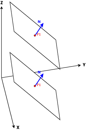
Both planes are defined by a point (P1 and P2) and their common normal N. If the input image is a binary image, it is first labeled. If it is label image it is used as is.
Two oblique plane images are then extracted and their histograms are computed. The output binary image is finally computed keeping the labels for which the histogram value is not null on both planes.
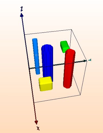
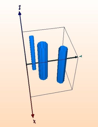
Figure 1. The Axis Connectivity algorithm applied on a segmented volume
(a) the input label image to process, (b) the selected planes, (c) the binary image retaining the connected objects between both planes
See also
Access to parameter description
Given two parallel planes and a binary (or label) input image, this algorithm generates a binary image containing each region that has a label present in both planes. If two disconnected regions with the same label are present on each plane, they are retained by the algorithm even if they do not cross the entire volume. To avoid this issue, the regions of the input image should be identified using a connected-component labeling algorithm; for example, by using the Labeling3d algorithm. If the input image is binary, this preliminary labeling step is automatically applied by the algorithm.
Both planes are defined by a point (P1 and P2) and their common normal N. If the input image is a binary image, it is first labeled. If it is label image it is used as is.
Two oblique plane images are then extracted and their histograms are computed. The output binary image is finally computed keeping the labels for which the histogram value is not null on both planes.
 (a) |
 (b) |
 (c) |
(a) the input label image to process, (b) the selected planes, (c) the binary image retaining the connected objects between both planes
See also
Function Syntax
This function returns outputBinaryImage.
// Function prototype
std::shared_ptr< iolink::ImageView >
axisConnectivity3d( std::shared_ptr< iolink::ImageView > inputObjectImage,
                    iolink::Vector3i32 originPoint,
                    iolink::Vector3d planeNormal,
                    iolink::Vector3i32 extremity,
                    std::shared_ptr< iolink::ImageView > outputBinaryImage = NULL );
This function returns outputBinaryImage.
// Function prototype.
axis_connectivity_3d( input_object_image,
                      origin_point = [1, 1, 1],
                      plane_normal = [0.57735002040863037, 0.57735002040863037, 0.57735002040863037],
                      extremity = [1, 1, 1],
                      output_binary_image = None )
This function returns outputBinaryImage.
// Function prototype.
public static IOLink.ImageView
AxisConnectivity3d( IOLink.ImageView inputObjectImage,
                    int[] originPoint = null,
                    double[] planeNormal = null,
                    int[] extremity = null,
                    IOLink.ImageView outputBinaryImage = null );
Class Syntax
Parameters
| Class Name | AxisConnectivity3d |
|---|
| Parameter Name | Description | Type | Supported Values | Default Value | |
|---|---|---|---|---|---|
 |
inputObjectImage |
The binary or label input image. | Image | Binary or Label | nullptr |
 |
originPoint |
The X, Y, and Z pixel coordinates of a point P1 of the first plane. | Vector3i32 | >=0 | {1, 1, 1} |
 |
planeNormal |
The X, Y, and Z coordinates of the normal N to both planes. | Vector3d | Any value | {0.57735002040863037f, 0.57735002040863037f, 0.57735002040863037f} |
 |
extremity |
The X, Y, and Z pixel coordinates of a point P2 of the second plane. | Vector3i32 | >0 | {1, 1, 1} |
 |
outputBinaryImage |
The binary output image which contains the retained objects. Its dimensions are forced to the same values as the input. | Image | nullptr | |
Object Examples
auto foam_sep = readVipImage( std::string( IMAGEDEVDATA_IMAGES_FOLDER ) + "foam_sep.vip" );

AxisConnectivity3d axisConnectivity3dAlgo;
axisConnectivity3dAlgo.setInputObjectImage( foam_sep );
axisConnectivity3dAlgo.setOriginPoint( {1, 1, 1} );
axisConnectivity3dAlgo.setPlaneNormal( { 0.57735, 0.57735, 0.57735} );
axisConnectivity3dAlgo.setExtremity( {1, 1, 1} );
axisConnectivity3dAlgo.execute();

std::cout << "outputBinaryImage:" << axisConnectivity3dAlgo.outputBinaryImage()->toString();
foam_sep = imagedev.read_vip_image(imagedev_data.get_image_path("foam_sep.vip"))

axis_connectivity_3d_algo = imagedev.AxisConnectivity3d()
axis_connectivity_3d_algo.input_object_image = foam_sep
axis_connectivity_3d_algo.origin_point = [1, 1, 1]
axis_connectivity_3d_algo.plane_normal = [ 0.57735, 0.57735, 0.57735]
axis_connectivity_3d_algo.extremity = [1, 1, 1]
axis_connectivity_3d_algo.execute()

print( "output_binary_image:", str( axis_connectivity_3d_algo.output_binary_image ) )
ImageView foam_sep = Data.ReadVipImage( @"Data/images/foam_sep.vip" );

AxisConnectivity3d axisConnectivity3dAlgo = new AxisConnectivity3d
{
    inputObjectImage = foam_sep,
    originPoint = new int[]{1, 1, 1},
    planeNormal = new double[]{ 0.57735, 0.57735, 0.57735},
    extremity = new int[]{1, 1, 1}
};
axisConnectivity3dAlgo.Execute();

Console.WriteLine( "outputBinaryImage:" + axisConnectivity3dAlgo.outputBinaryImage.ToString() );
Function Examples
auto foam_sep = readVipImage( std::string( IMAGEDEVDATA_IMAGES_FOLDER ) + "foam_sep.vip" );

auto result = axisConnectivity3d( foam_sep, {1, 1, 1}, { 0.57735, 0.57735, 0.57735}, {1, 1, 1} );

std::cout << "outputBinaryImage:" << result->toString();
foam_sep = imagedev.read_vip_image(imagedev_data.get_image_path("foam_sep.vip"))

result = imagedev.axis_connectivity_3d( foam_sep, [1, 1, 1], [ 0.57735, 0.57735, 0.57735], [1, 1, 1] )

print( "output_binary_image:", str( result ) )
ImageView foam_sep = Data.ReadVipImage( @"Data/images/foam_sep.vip" );

IOLink.ImageView result = Processing.AxisConnectivity3d( foam_sep, new int[]{1, 1, 1}, new double[]{ 0.57735, 0.57735, 0.57735}, new int[]{1, 1, 1} );

Console.WriteLine( "outputBinaryImage:" + result.ToString() );